- Navigation System
-
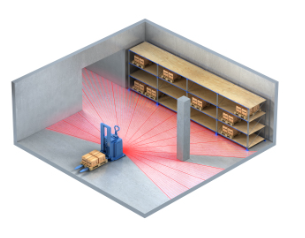
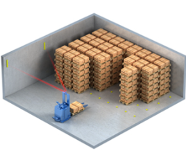
- Laser Scanner
-
- Detects walls and other surfaces
- SICK S200 and S3000 are available
Natural Navigation uses measurements from a laser range sensor to recognize landmarks such as walls and other surfaces. The vehicle’s position is continuously updated based on encoder data that tracks its movement. Additionally, the position is refined using measurements from walls and other objects. The navigation system always remains active.
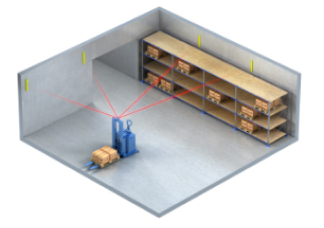
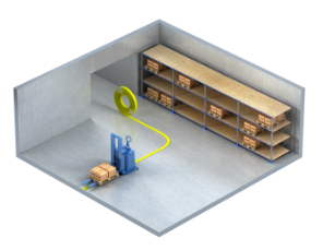
Laser Navigation utilizes reflector-based landmark localization to enable autonomous vehicle guidance. The system continuously updates the vehicle’s position using data from fixed reflectors. Positional corrections are made through triangulation of laser measurements to known reflector coordinates. The navigation algorithm always remains active to ensure real-time positional accuracy and reliability.
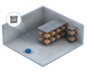
Barcode Navigation employs floor-mounted barcodes to enable accurate positioning in open environments where structural landmarks (e.g., walls) are unavailable, limiting the use of other navigation systems. Its modular and easy-to-install design provides a flexible alternative to fixed infrastructure solutions, such as spot navigation systems that rely on embedded magnetic markers drilled into the floor.
Magnetic Tape Navigation is based on free guidance using landmarks such as magnetic tape and distance markers. The vehicle’s position is continuously updated by referencing these landmarks. Additionally, encoder data is used to track vehicle movement and enhance position accuracy. Position corrections are made through measurements to the magnetic tape and distance markers. The navigation always remains active.
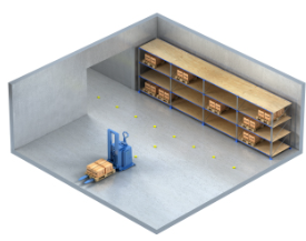
Spot Navigation is based on free vehicle guidance using fixed landmarks, specifically magnets embedded in the floor. The vehicle’s position is continuously updated by referencing these landmarks. Encoder data is simultaneously used to track vehicle movement and ensure reliable position estimation. Position updates are performed through measurements to the spot magnets, and the navigation system remains active at all times.
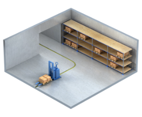
Inductive Wire Navigation operates on free guidance principles using landmarks such as inductive wires and distance markers. The vehicle’s position is continuously updated by referencing these landmarks. Encoder data is used in parallel to track vehicle movement and support accurate position calculation. Position updates are achieved through measurements taken relative to the inductive wires and distance markers, ensuring the navigation system remains active at all times.
Range Navigation utilizes data from the Laser Range Scanner to identify environmental landmarks such as walls and flat surfaces. This method is particularly effective in structured environments like corridors, where consistent reflective surfaces are present. The vehicle’s position is continuously updated using measurements from the scanner, supported by encoder data to track movement. Accurate localization is maintained through consistent referencing of walls and other planar surfaces, ensuring the navigation system remains active at all times.
Multi Navigation enables a vehicle to dynamically switch between different navigation methods during operation. This approach combines the flexibility of reflector-based navigation with alternative navigation techniques, making it particularly advantageous in factory environments where installing reflectors may not be feasible in certain zones.
AGV system should be designed with consideration of safety as the first priority.RUSSELL ROBOTICS provides AGV system comprising safety functions into both AGV and AGV control system to minimize potential hazards to operating personnel, including protection of fixed assets or mobile assets.


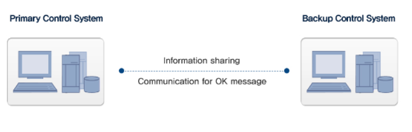
All primary AGV components are connected via an internal network, with the vehicle controller acting as the master node. The controller is responsible for initializing, configuring, and supervising all devices connected to the network. It operates in two distinct states: Normal State and Safe State. Upon system startup, the controller defaults to Normal State, executing the full range of AGV functionalities as defined.
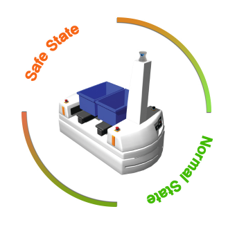
If a functional error is detected—either by a device on the network or by the controller itself—the master logs the fault using a system event code and transitions into Safe State. The Safe State is a passive operational mode that allows only diagnostic tasks to be performed, ensuring system safety.
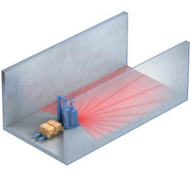
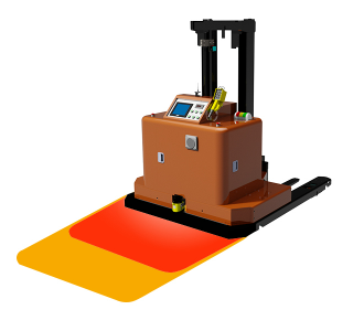
To prevent collisions, each vehicle is equipped with at least one programmable obstacle detection sensor. These sensors operate with two simultaneous protective zones: an outer zone and an inner zone. If an object enters the outer zone, the vehicle reduces speed to a preset limit. If the object breaches the inner zone, the vehicle comes to an immediate stop.
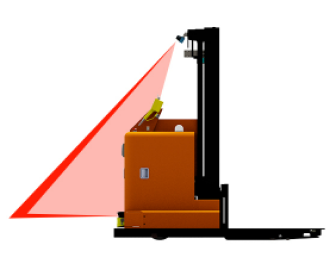
Typically, laser-based obstacle detection sensors have a horizontal field of view. To ensure comprehensive coverage, multiple sensors can be mounted at different heights on the same side of the vehicle, as illustrated. This setup enables protection against collisions in both horizontal and vertical directions.
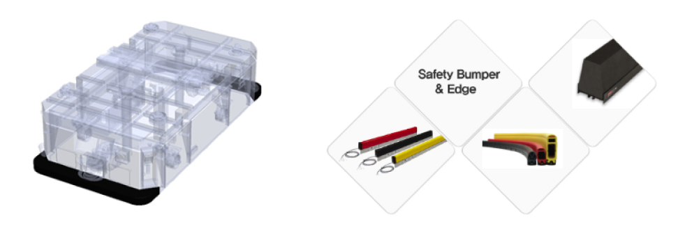
The safety bumper is mounted around the vehicle chassis to protect both personnel and the vehicle from injuries and damage caused by collisions. As a critical component of the AGV safety circuit, it remains operational even when the AGV is in an uncontrollable state. When external pressure is applied, the normally open circuit inside the bumper closes, sending a signal to the controller. Upon activation, the safety bumper functions as an emergency stop mechanism by cutting power to the AGV. It is available in various shapes and sizes to accommodate different types of vehicles.

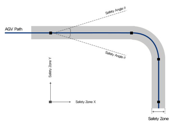
To ensure the vehicle follows the AGV path as intended, a safety zone must be defined within the vehicle application. This safety zone is typically established using a rectangular area and an angular limit. If the vehicle's reference point falls outside this rectangle or if its orientation relative to the AGV path exceeds the defined angle threshold, it is considered outside the safety zone. When this occurs, the vehicle is no longer permitted to operate in automatic mode. Instead, it will decelerate and come to a stop using the emergency stop slope.
It is recommended to install instruments related to safety functions on the AGV. Since these devices are programmable, their functions can be customized through a PLC program integrated into the vehicle application, allowing optimization for specific site conditions. The following devices are typically considered essential and are commonly installed on AGVs.


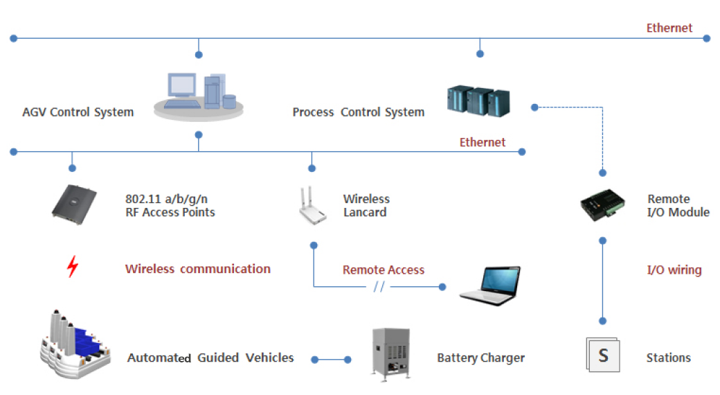
RUSSELL ROBOTICS delivers a comprehensive AGV system that integrates all aspects of automated material handling, incorporating both hardware (HW) and software (SW) components. The solution supports not only seamless AGV movement between stations but also enables reliable interfacing with external systems or equipment. The AGV system is typically configured as illustrated in the figure below; however, the configuration is flexible and can be adapted based on specific system requirements.
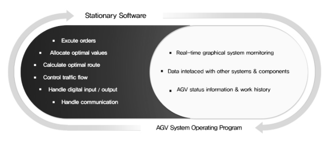
The AGV Control System (ACS) comprises two main components: Stationary Software and the AGV System Operating Program. The Stationary Software forms the foundational layer that supports transportation tasks within the AGV system, operating in the background. In contrast, the AGV System Operating Program facilitates integration with other systems and components, offering a wide range of user-friendly interface functions for effective control and monitoring of the AGV system.
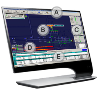
Generally, HMI is configured as shown below figure. However required functions can be added by request of customer.
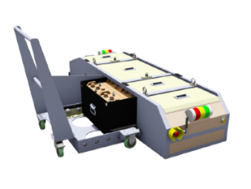
As AGVs are powered by batteries, an optimized battery charging plan is critical for the reliability and uptime of AGV/AMR systems. Developing such a plan requires careful consideration of battery type, capacity, power consumption rate, and the AGV's operational profile. Typically, opportunity charging or battery exchange methods are adopted based on the system’s operational demands.

If there is an AGV in low battery state in the system, Control System doesn't allocate any good transport order to it and it drives to the designated place and waits for battery manual exchagnig at there. once battery exchanging was completed manually and AGV was recovered from low battery status, then AGV is allowed to be in the system by Control System.
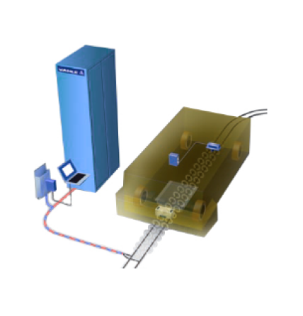
IPT(Inductive Power Transfer) System supplies the required power to the AGV by non-contact method based on technology of high-frequency transformation. Also wire installed under floor can be used to support vehicle guidance as introduced in Inductive Wire Navigation system by interface with specialized guide sensor on the vehicle.
The NDC platform, developed and provided by Kollmorgen, is a versatile, fully integrated, and scalable control system designed to support a wide range of Autonomus Guided Vehicles (AGVs) from compact, simple units to large-scale, complex systems. As a recognized member of the Kollmorgen Partner Group, RUSSELL ROBOTICS not only supplies AGV systems built on the NDC architecture but also delivers comprehensive training and support services for the deployment and operation of NDC solutions.
NDC works with all established navigation technologies. Advanced navigation technology Natural navigation introduced above video, is a concept for navigation in the existing environment. By using Natural navigation there is no need to install reflectors and markers, leading to lower commissioning costs.
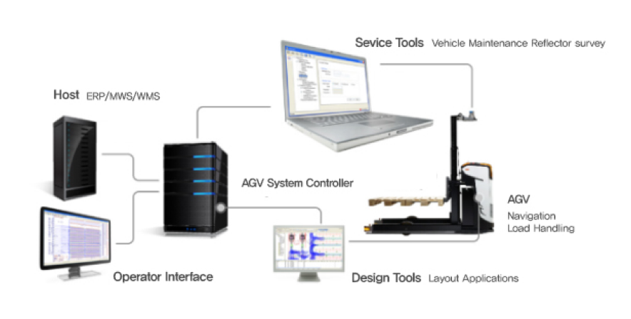
NDC gives you access to a set of effcient design and service tools. The design tools helps you outline all kinds of layouts as well as system and vehicle applications. Service tools include vehicle maintenance (e.g. fault-training, statistics and software downloads) and automatic surveying of the environment.
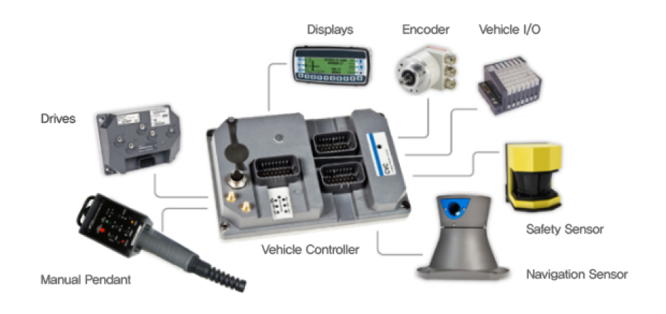
NDC hardware consists of powerful and reliable components in a number of areas. All components are designed for tough environments where vibrations, dust, moisture and temperature vibrations are all part of daily life.
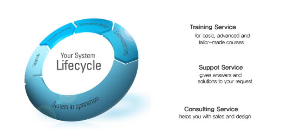
End-users require high uptime, efficient daily operations and applications that are easy to change.
we help you meet these demands with NDC services. Our service portfolio consists of training service, support service and consulting service.
RUSSELL ROBOTICS has supplied various types of AGVs that operate using PLC-based control solutions. A key advantage of PLC systems is that they offer maintenance personnel a user-friendly and easily accessible control environment. When used as a vehicle controller, the PLC manages all driving functions by interfacing with navigation sensors and oversees all critical components related to safety and load handling.
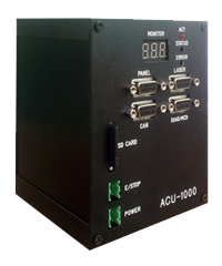
The ACU 1000 Series, developed by RUSSELL ROBOTICS, offers a specialized controller designed exclusively for driving control. It supports all floor-based guidance methods and accommodates various driving patterns along with other solutions. For complex load handling or additional functions, integration with an auxiliary controller such as a PLC can be used. An integrated design tool is also provided, enabling easy vehicle application development and offering diagnostic functionalities.